Macro PU Installation Checklist
How to access the Partner Portal (internal)
- Go to smart3d.tech/smart3d-partners using your preferred web browser.
- Enter password: smartpartner

- Now you have access to all our internal partner material.
IMPORTANT: Do not hesitate to share your suggestions to add valuable documents and information to the Partner Portal.
If you need any further assistance, feel free to contact us at CSOps@smart3d.tech
Unboxing
It’s important to follow this procedure to ensure a correct start up.
The procedure is divided in two (2) sections: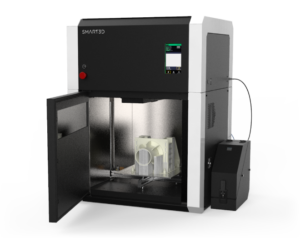
- Unboxing
- Setting up
If there is a problem during any of the provided steps, please let the technical support know before proceeding via email at
Before Unboxing
Make a visual inspection of the box for visible shock and inspection of external shock sensors. This should be done BEFORE the dispatch service leaves the site and in case the sensors are activated, a note must be left with them on the delivery receipt.
Included with each Macro PU
4x Collet clips
1x Magnetic PEI sheet
1x Power Cord Cable with regional Plug
1x Hex key set for Hotends
1x Thermal Paste
1x Set of M3 Heater and Thermistor retainer screws
1x Pair of thermal protective gloves
1x Adhesive
2x Bottles of Coolant Liquid
2x Teflon tubes
2x DryFeed™
2x USB cables
2x Silica gel packets
Required items
- Wirecutter or pliers
- Crowbar or a flat screwdriver with a hammer
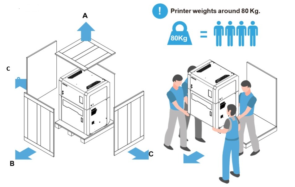
- 3 to 4 people to lift the Printer (80kg)
- Hex keys
Unboxing (25-30 minutes)
- With a screwdriver, remove the crate panels in the following order:
- A) Top
- B) Front
- C) Sides
- Remove the printer carefully from the pallet with a pallet jack/forklift. To ensure the integrity of your printer, the unit should be moved by at least four (4) people.
Site preparation
The Macro PU 3D Printer is for indoor use only. Place the unit on a firm and stable surface that can accommodate the printer’s weight and dimensions, plus required clearances:
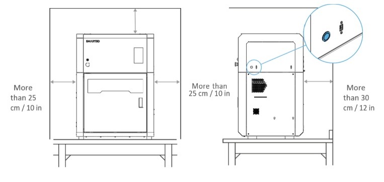
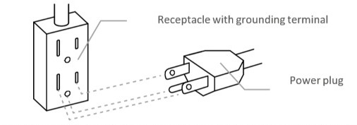
Always ground the unit
Connect the Macro PU to a grounded power source. Do not defeat or bypass the ground lead.
- Plugin the female end of the supplied power cord directly into the socket located on the back of the printer.
- Plugin the male end of the power cord directly into a grounded electrical outlet.
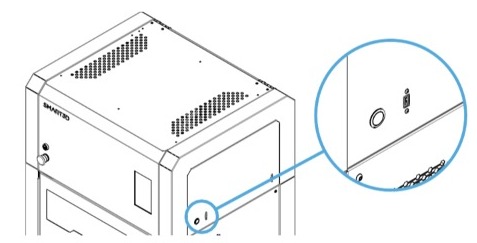
- Press the Power button located on the right side of the printer (see image above).
After installation: Take measures to prevent the unit from falling in case of an earthquake, high impacts, etc. as it could lead to personal injury.
Inspecting and Setting up the printer
Before plugging in your printer:
1. Perform a visual inspection of your printer, looking for any bumps or scratches, and inspection of internal bump sensors.
If the internal shock sensors are activated, the machine could have suffered a severe shock, affecting its correct operation. You should proceed to initiate the claim with the dispatch company.
Check the front glass door. Open the door and check the inside, nothing should be loose.
IMPORTANT: Report anything out of the ordinary to technical support for warranty purposes.
2. Open the front door. Remove the protective foam from the resistors by sliding them towards the center.
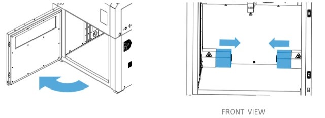
a. Open the top door to remove the four (4) zip ties securing the axis using a set of pliers and check the printhead can move freely. Be careful not to damage the belts.
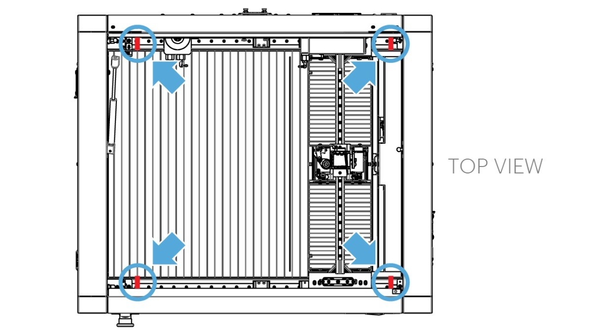
Manually move the printhead gently and slowly from left to right and front to back (15 cm in each direction should be sufficient). If you're unable to move the printhead, that means you have missed cutting one of the zip ties.
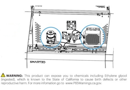
3. Check the liquid cooling repository for any leaks. If there is, contact technical support.
CAUTION: Wash your hands if you come into contact with the coolant and avoid touching your eyes, nose, or mouth.
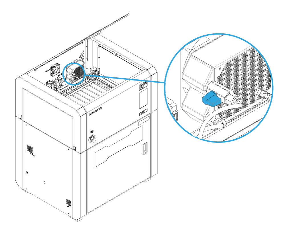
Check the condition of the liquid cooling system tubing. The tubing should not be bent or twisted.
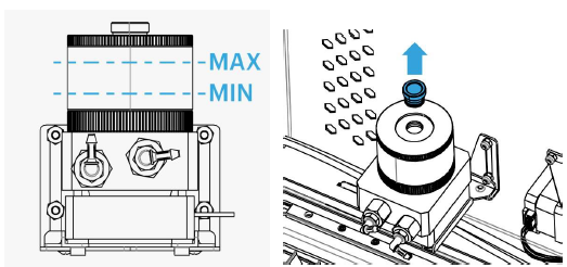
a. Open the cooling system stopcock as shown
b. Remove the reservoir top (be careful not to lose its O-Ring) and fill the reservoir with the included Smart3D liquid coolant.

c. After filling up your cooling system, plug in the power cord and turn on the Macro PU.
The system will begin to purge the existing air in the pump.
Keep filling the reservoir to the specified max level (see level image in step 3.b) until the coolant in the reservoir no longer drains when the unit is on. Then put on the reservoir top and open the fill port.
After filling up your cooling system, we recommend letting your unit run for at least 30 minutes without printing with the fill port open to vent as many air bubbles as possible. This will help improve the longevity of your cooling system.
When completed, close the fill port and the top door.
4. Setting up the Smart3D DryFeed™ units
The DryFeed™ units are a key component, to keep filament dry and protected from dust.
 Inside the DryFeed™ you will see that each one has an identifying label.
Place DryFeed™ T0 on the right side and T1 on the left side of the printer.
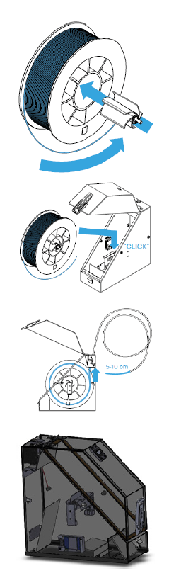
Connect the support pins of the DryFeed™ over the mount slots on each side of the Macro PU and slide the DryFeed™ down until the support pins fit snugly into the mount slots.
Connect the USB cables from each DryFeed™ unit to the rear USB port on each side of the Macro PU.
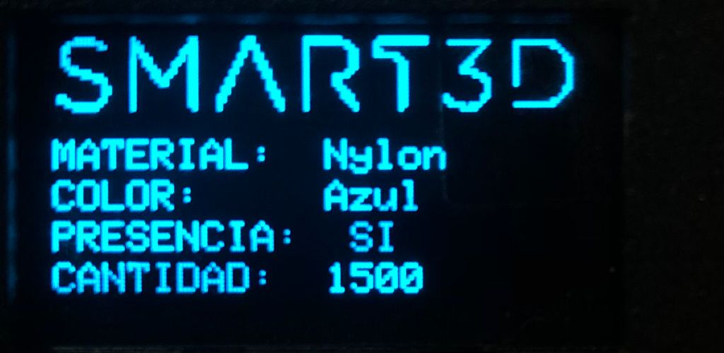 Inside of it, there is an RFID reader, thanks to which, when the printer is turned on, on the DryFeed™ screen, you will be able to see the type of filament, quantity, color and status of the filament sensor.
Insert the Bowden tubes into each DryFeed™ unit's Bowden connector and lock them with collet clips (Orange U-shaped piece). The other end will be let loose. After the filament loading sequence, the Bowden tube will automatically connect to the Macro PU. 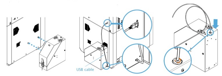
Important: The DryFeed™ units must be connected before turning on the printer.
5. Loading Filament Spool
NOTE: To obtain a good quality print, it is important that the filament is dry. Remember that the presence of moisture will affect the completion and quality of your parts.
Important: It is recommended to put a silica bag inside the DryFeed™ to keep the filament dry.
Important: In order to validate the correct operation of the printer, it is necessary to use S3D filaments and printing profiles, otherwise, the good quality of the objects cannot be guaranteed.
Do not use filaments or any slicer other than the one from S3D.
a. Open the Smart3D DryFeed™.
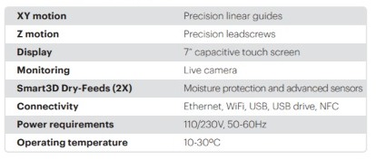
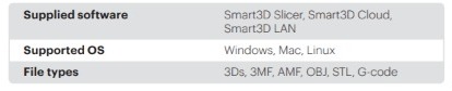
b. Insert the Spool adapter into the Filament Spool (pressing the piece from the right to the left) and place it into the Spool Holder adding a little of pressure until you hear a click. The adapter has a small slot that should be on the right side of the spool.
c. Be sure to place the filament in the correct orientation (with the tip of the filament coming from above). Place Filaments of 1Kg or below in the bottom groove, and Filaments of 2Kg in the upper one.
Note: the filament must rotate following the arrow in the image.
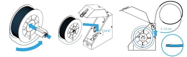
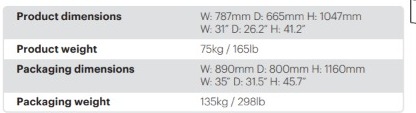
d. Push the filament through the Smart3D DryFeed™ hole and keep pushing until you can spot the end of the filament coming out of the Bowden. After this, push further until 5-10cm are coming out from the tip of the Bowden end. If the filament doesn’t enter easily through the DryFeed™.
Feed the filament into the push-in connector on the back of the Macro PU until you feel a resistance (the filament reaches the extruder).
Be careful not to push filament too hard. When you feel the resistance, the extruder should be able to grab and pull in the filament. The rest of the process is automatic.
Start the Load the filament procedure from the unit's touchscreen.
Once the hotend has reached the target temperature, make sure the extruder starts feeding the filament to the hotend. If it doesn't, push the filament in until you feel the extruder grabbing and feeding the filament.
IMPORTANT: Facing the front of the printer, extruder T0 is located on the right and T1 on the left.
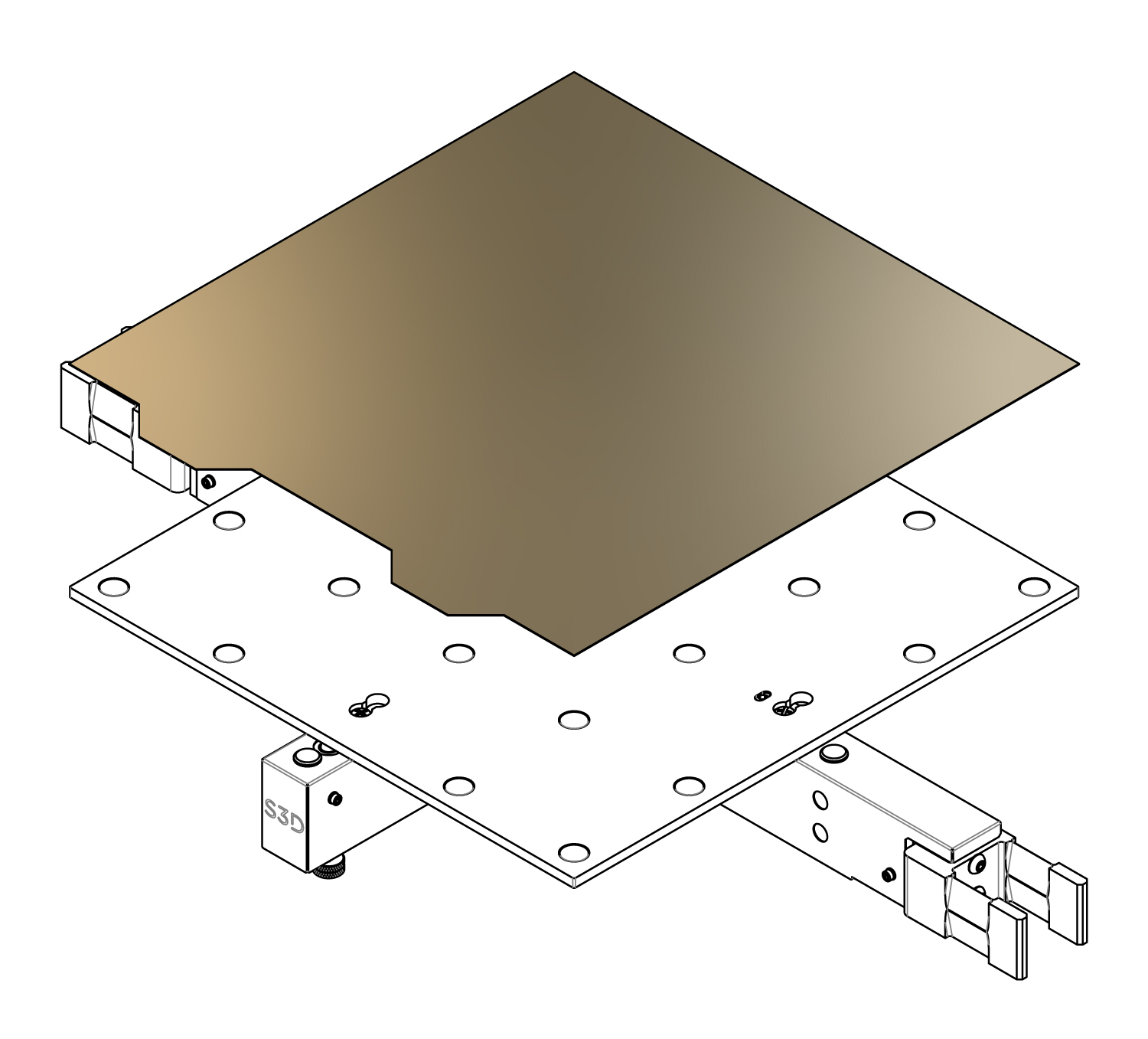
6. Place the build plate
a. Log into your Macro PU on a PC.

b. We are going to indicate the actual position of the build plate by sending command G92 Z400 in the command line at the top of the screen. The Macro PU will believe that its current position is Z400.
c. Now raise the build plate by typing sending command G1 Z250.
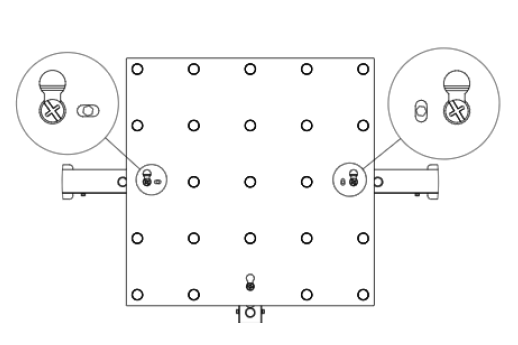
d. Remove the three (3) screws displayed in the image below.

e. Align the highlighted holes in the bed with the screw holes from the previous step.
Be sure the bed hooks with the ball joint screws.
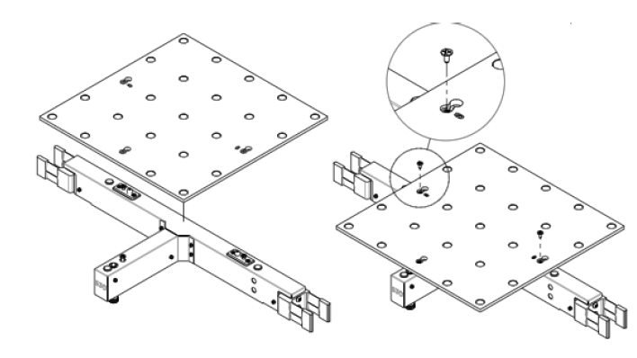
f. Push each screw upwards by hand and affix to the bed.
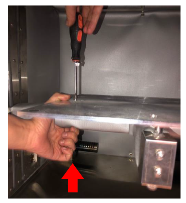
The screws should look like this when the bed has been properly affixed.
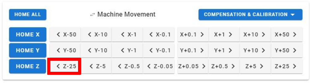
7. Verify that the build plate is parallel with the print head.
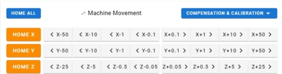
Send the print head to position X0 Y0, by pressing HOME X HOME Y.

Slowly bring the build plate closer to the print head by pressing the Z-25 button.
WARNING: make sure that the nozzle doesn’t crash with the build plate.
Then move slowly the print head to the other end (X 350), by pressing the button X + 50.
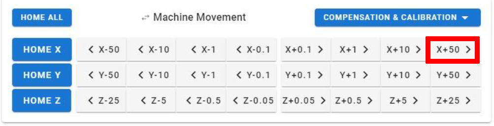
Check that the build plate is parallel to the print head by measuring 5mm distance between the front right end of the build plate and the nozzle.
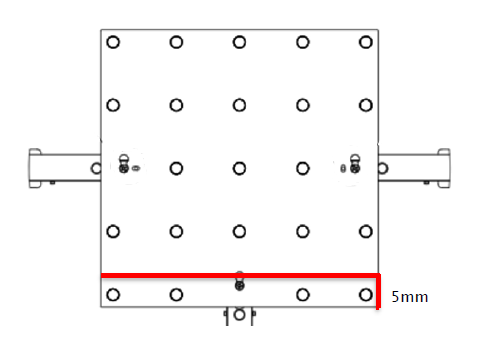
NOTE: If it is not parallel, with your hands, grab the bed from the front right end, and move it.
8. Place the PEI sheet.
You can download the complete unboxing guide by clicking here.
After Unboxing
Once you have finished with the unboxing, it is very important to follow the calibration procedures listed below;
NOTE: it extremely important to read and follow these instructions very precisely.
NOTE: It is very important that when executing a mesh compensation the machine is continuously supervised to cancel the operation if it sees a possible collision with the build plate.
Safety recommendations
- The Unit is equipped with a 3-pin plug with incorporated ground, which must be inserted in a grounded wall socket only. Do not defeat or bypass the ground lead.
- Always wear personal protection equipment.
- Maintain the recommended range of temperature (30°C /86°F) and humidity in the equipment area.
- Do not use this product in an environment containing volatile or flammable compounds.
- Know the location of fire extinguishers and how to use them. Use only ABC-type extinguishers on electrical fires.
The door and the top door connote be opened during the printing process. Keep the top door clear from any object.
Both linear guides and leadscrew need maintenance every three months. You will need grease to lubricate the items.
Problems due to shipping
- Check for any visible damage to the printer. Contact customer support if the impact indicator has been activated (turned red) as this indicates that the printer was subject to an impact.
- Perform a HOME ALL and verify that...
- The endstops are working correctly (If this fail, contact customer support)
- The inductive sensor is working correctly (If this fail, contact customer support)
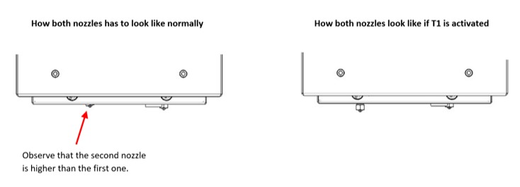
- Both nozzles are positioned correctly (If this fail, contact customer support)
- The build plate is calibrated correctly.
WARNING: If the nozzle crashes into the build plate during the homing procedure, immediately press the EMERGENCY STOP button.
If the nozzle crashes into the build plate...
- Make sure both the nozzle and build plate are clean
- Download our build plate calibration guide and be sure the build plate is properly calibrated
About the Macro PU
The Macro PU is a modular solution that provides industrial reliability and speed with an open material platform, conceived to streamline the process from development to production.
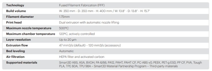
With its large actively heated chamber of 350 x 350 x 400 mm (13.8 x 13.8 x 15.7 inches), it allows the printing of big parts at high temperatures, in virtually any 3D printing material available as ABS, ULTEM, PP, Nylon, and PEEK.
Properties
Mechanics and Electronics
Software
Size and weight
You can download the Macro PU specifications from here.
Do NOT
- Do not open the front and top door during the printing process (this will pause the print and drastically reduce the chamber temperature)
- Do not store objects on top of the top door
- Do not use the printer without the proper level of cooling liquid
- Do not use different materials with the same hotend/nozzle
- Do not install the printer where flammable gas or corrosive gas is generated
- Do not install the printer where ambient temperature exceeds 30 °C (86 °F)
- Do not use the printer if the linear guides and leadscrew are not properly greased
- Do not start printing if the nozzle and/or the build plate are not clean.
.
Filament loading recommendations
- Verify that the spool is correctly positioned inside the feeder
- Check that the filament is not tangled inside the feeder
- Cut the filament tip to be inserted in the extruder at 45 degrees.
WARNING: Use a different hotend for each material. If you are going to print with carbon fiber materials or high-temperature polymers clients will have to purchase a Smart3D Abrasive kit or a Smart3D HT kit.
Click on the following link to know how to change the Hotend;
Loading filament
NOTE: To obtain a good quality print, it is important that the filament is dry. Remember that the presence of moisture will affect the completion and quality of your parts.
Important: It is recommended to put a silica bag inside the DryFeed™ to keep the filament dry.
1. Open the Smart3D DryFeed™.
2. Insert the Spool adapter into the Filament Spool (pressing the piece from the right to the left) and place it into the Spool Holder adding a little pressure until you hear a click. The adapter has a small slot that should be on the right side of the spool.
3. Be sure to place the filament in the correct orientation (with the tip of the filament coming from above). Place Filaments of 1Kg or below in the bottom groove, and Filaments of 2Kg in the upper one.
Note: The filament must rotate following the arrow in the image.
4. Push the filament through the Smart3D DryFeed™ hole and keep pushing until you can spot the end of the filament coming out of the Bowden.
After this, push further until 5-10cm is coming out from the up of the Bowden end.
As can be seen in the image, the DryFeed™ has two metal sheets that prevent the filament from unwinding. Verify that the spool is correctly positioned and that these plates are placed touching the spool edge, thus preventing the filament from coming out.
5. Close the Smart3D DryFeed™ and secure the latch.
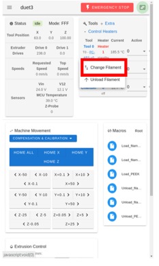
6. On the Tool section, press the T0 or T1 button, depending on where you are going to load the filament, and press Load Filament.
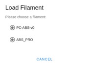
The following pop-up will appear.
Select the filament you are going to inset from the list.
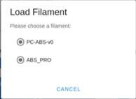
7. The following pop up will appear,

Feed the filament into the push-in connector on the back of the Macro PU until you feel a resistance (the filament reaches the extruder).
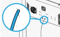
Note: It is recommended to cut the tip of the filament at a 45° angle before feeding it into the extruders.
8. Make sure the extruder starts feeding the filament to the hotend. If it doesn't, push the filament in until you feel the extruder grabbing and feeding the filament.

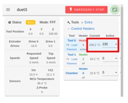
9. The hotend will start to heat up.
You can observe this in the tool section.
10. Once it has reached the target temperature, the machine will start to extrude the filament from the nozzle.
11. Once finished, the following pop-up will appear.

The Bowden tube will automatically connect to the push-in connector on the Macro PU while loading. To remove it, push the blue collect on the connector and pull the tube out. If it's stuck, replace the connector.
Unloading filament
 On the Display screen, go to the Home screen.
On the Tool section, press the T0 or T1 button, depending on where you are going to unload the filament, and press Unload Filament.
The next pop-up will appear, please wait till the nozzle is heated up.

Once it has reached the target temperature, the extruder will retract the filament. The following pop-up will appear telling you that the filament is being removed.

Note: it is recommended to use a different hotend for each type of filament.
Changing filament
- On the Tool section, press the T0 or T1 button, depending on where you are going to change the filament, and press Change Filament.
- Select the new filament from the list that will appear where the currently loaded filament is pre-selected.
- The nozzle will start to heat up, wait till it finishes.

- Once it has reached the target temperature, the extruder will start to retract the filament. Open the DryFeed™ cover and manually pull the filament from the tube. Grab the tip of the filament and lock it on the spool in a way to prevent it from unwinding itself. The DryFeed™ can be closed now.
Note: It is recommended to use a different hotend for each type of material.
- Insert the previously selected filament in the extruder and press OK.

- Follow the loading filament instructions from step 7.
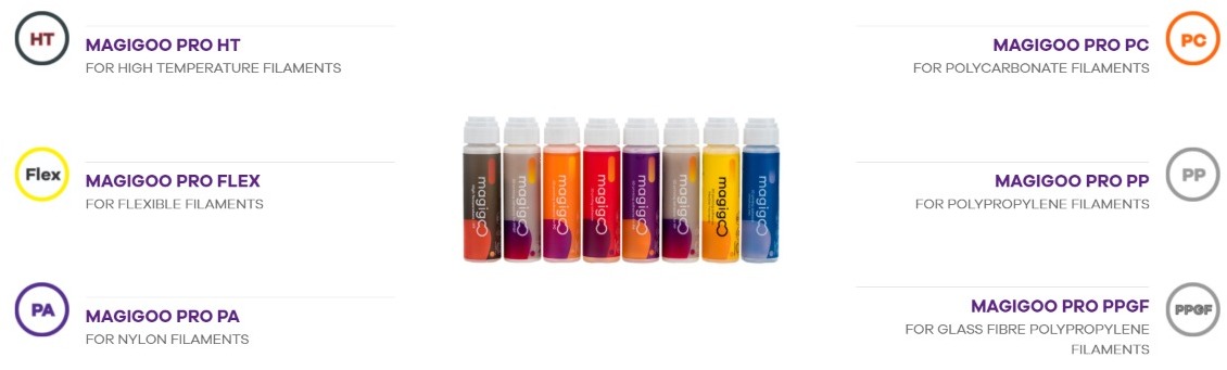
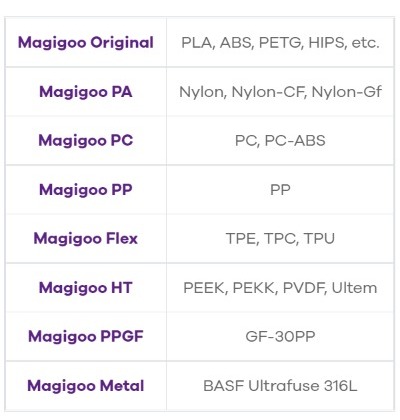
Magigoo
Recommended for any material.
Adhesives are easy to use and only require that you apply them by spreading a thin coat on your build-plate, printing and then easily removing the part.
As an interface layer, these glues will increase the adhesion of the printed first layer to your build-plate substrate.
Dimafix
Recommended for ABS, PLA, NYLON, or any other low-temperature material.
Nanopolymer
Designed for PEEK, Ultem, PPSU, and other high-performance FDM polymers, this build plate glue works for nearly every filament - Nylon, ABS, PLA, PETG, PEI, PSU, and every filament we've tested so far.
How to apply it
Before applying,
- Shake the glue pen,
- Press down the nib on the printing bed for Magigoo or dimafix to flow.
- Spread more or less evenly on the printing area. It is enough to cover your active print area with an even thin layer.
N.B. DO NOT SQUEEZE the bottle to avoid the applicator popping off. Applicator has a valve which is activated once you push on it.
It is best to apply it when the printing bed is cool, but it will also work if applied on an already hot print bed. Make sure to use the adhesive with suggested plastics and with correctly leveled bed and suitable printing settings. See recommended settings below.
How to connect to Internet
In order to use the printer interface on any computer, the Printer must be connected to a WIFI network or use an ethernet cable to connect it to the internet.
How to connect to WIFI
First, a keyboard must be plugged into the USB port next to the power button.
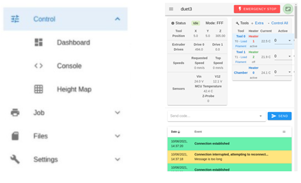
Then, in the hamburger menu, go to Control >> Console.
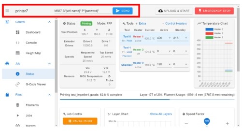
Once you are connected to the printer interface, write the following command;
M587 S"WIFI name" P"Password"
S"WIFI name" Network name
P"Password" Network password
Do not forget to write the WIFI name and the Password between quotes ""
NOTE: If an error occurs, it may be due to a problem with your internet connection. Reset the router, verify that the machine is within range, and check that your Wi-Fi connection is 2.4G and NOT 5G.
How to connect using an ethernet cable
Another option to connect the printer to the Internet is using an ethernet cable.
Just above the printer's power socket is the ethernet port. Connect one end of the cable here and the other into the router.
How to connect to your printer from a computer
To log into your Macro PU on a PC, enter the following in the address field in any web browser:
PU-LT-[Unit Serial Number].local/

Your unit's serial number is available on the model identification tag on the back of the unit next to the power socket or the touchscreen.
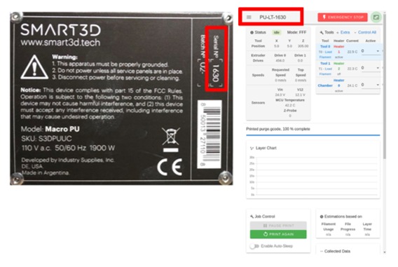
After logging in, you will have access to the command screen of your Macro PU via your computer.
Inside the accessory kit, you can find a label with the serial number of the printer, which you can paste and place where you want to have it close.

How to send to print
Note: Before starting any print, be sure that both the nozzle and the build plate are clean.
WARNING: Use a different hotend for each material. If you are going to print with carbon fiber materials or high-temperature polymers clients will have to purchase a Smart3D Abrasive kit or a Smart3D HT kit.
How to upload a G-Code
The Jobs section situated in Files menu allows G-Code files to be run, simulated, uploaded, downloaded, edited, renamed, deleted, and organized. A summary of the print time and other information is shown.
Note: it is recommended to do this procedure using the web interface.
It is possible to upload a G-code in several different ways.
Using the Macro screen
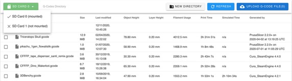
G-Code files can be uploaded by inserting a USB into the USB port right next to the power button, click on the SD card button, search and select the desired file.
To start printing, just click on the G-code you want, a popup will appear, press YES to start printing.
It is recommended not to upload files during a print to prevent interference while reading the SD card for an ongoing print, or possibly corrupting the uploaded file. A blue notification popup shows the upload progress.
Using the web interface
G-Code files can be uploaded by clicking the Upload G-Code File(s) button and browsing for them on your computer. The file you have selected will appear in this section
Additionally, the Smart3D slicer software can be set up to send files directly to the mainboard.
Subdirectories are created by clicking the New Directory button, then naming the directory. Files can be dragged and dropped into subdirectories to organize. To move a file out of a subdirectory, drag it to the directory path in the header.
The file list can be sorted by clicking on the relevant column header. A second click will reverse the direction.
You can also use the Upload and Start button in the header bar to quickly upload and start a print. Click this button, search for the file, and it will start automatically.
Prior to the launch of the print
- Do not send to print if the build plate and/or the nozzle are not clean (you should not see any type of filament residue).
- Do not open either the top or the front door when printing starts.
- Remember to apply the adhesive.
- Check that there is coolant liquid.
- Verify that all axis are properly greased
Start File
Note: It is important to keep the top door closed when the chamber is heated or preheated. Avoiding to do so could cause damage to the internal components of the printer since it will disrupt its active cooling system.
Clicking on a G-Code file in the file list will pop up a dialogue box to run the selected G-Code file.

Right-clicking on the file to open a menu with options to start the file, simulate, download, edit, rename or delete the file.
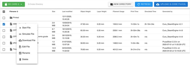
Selecting Start File from the right-click menu runs the file immediately; it does not prompt before starting.
Simulate File
The Simulate File option runs the file without heating or moving any axis. The firmware works out how long moves take and thus can determine an accurate estimate of the print time. When started, the screen switches to the Status screen to show the simulation progress. Simulations run much faster than real prints, typically taking a couple of minutes per megabyte of G-Code. Simulations can be paused and canceled from this screen. The results are reported as a popup (and in the console) and is added to the file list view on the Jobs screen, in the Simulated Time column.
Attention: It is extremely important to carefully supervise the first print of the machine, and verify its correct operation and calibration.
Calibration
The Calibration process takes place every time a new print file is sent to be 3D printed. This process will ensure a perfect first layer, which will drastically reduce the chance of a failed 3D print. To achieve this, the printhead will run an automated probing sequence that will measure several points on the PEI sheet to generate a digital representation of it, which later will be used as a digital guide by the printer itself to know at what height it should be printed.
Manual Calibration:
For the automatic calibration feature to work, the print bed should be aligned as parallel as possible to the X-axis and the PEI sheet correctly centered on the print bed. The Macro Prototyping Unit is shipped with an already calibrated print bed, so it’s not necessary to run a manual calibration unless a Smart3D Technician or certified representative requests it. If that’s the case, the manual calibration process will be provided by them.
How to use the printer interface
Main menu
The main menu can be hidden by clicking the 3-horizontal-bar icon on the left of the header bar and is divided into four categories, Control, Job, Files, and Settings.
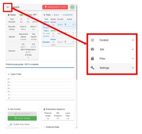
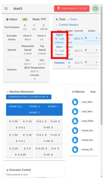
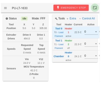
The Macro PU touch screen will always show you 2 main information boards:
status, machine mode (FFF - Fused Filament Fabrication), axis and extruder positions, speeds, VIN, microcontroller temperature, and Z-Probe reading.
Tools + Extra
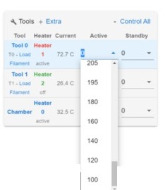 Extruders T0 and T1 are defined under Tools.
Tools can be in three states; Off, Active, and Fault. At startup, all tools are set to Off.
Extruders and chamber temperatures can be set here manually.
To start heating the hotend press over Tool 0 or Tool 1, and select the desired temperature by clicking on the arrow as shown.
By pressing a tool, you will activate it while setting the other tool to standby. You can set an active tool to standby by pressing on it. Printing and standby temperatures for the tools are set by the gcode but can be changed on the fly during printing.
If the status Fault appears press the restart button to continue.
Control
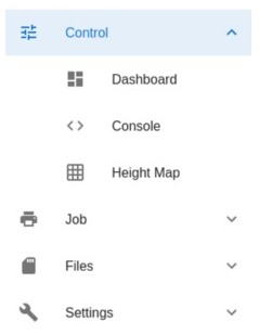 In the control category you will find:
Dashboard - The main screen for machine control when no prints are running.
Console - A terminal for entering G-code commands and viewing full response.
Height Map - Shows the results of the bed mesh compensation probing.
Dashboard
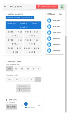
Machine Movement - Manual homing and movement controls of axes, bed compensation & calibration.
Compensation & Calibration - The first layer of a print must be printed at the right height, this calibration process adjusts the bed by generating and probing a grid of points for bed compensation.
Home and axes movement - In this section there are buttons to Home all axes at the same time or individually and to manually control the movement of individual axes.
To start moving freely the axes, first press ” HOME ALL", be sure that the PEI bed is correctly installed on the build plate, that the nozzle is clean and no objects are interfering with this process. When the process finishes, you can freely move the axes.
There is a notification box below the homing section that will indicate if axes have been homed. The homing status will be blue if the axes have been homed and orange if they have not.

Macros - shows the load filament and Unload filament option. There is also a special option for loading and unloading PEEK.
Extrusion Control - Manual controls for the active Tool. It allows manual extrusion or retraction of the currently active Tool. Retract and Extrude buttons will be greyed out if the temperature of the Tool is below the minimum required.
- Feed amount - You can select how many millimeters you wish to extrude or retract.
- Feed rate - The speed in millimeters per second you wish to use.
Fan Control – Allows the user to modify the layer cooling fans using a speed multiplier.
Note: This new feature will be available soon
Console
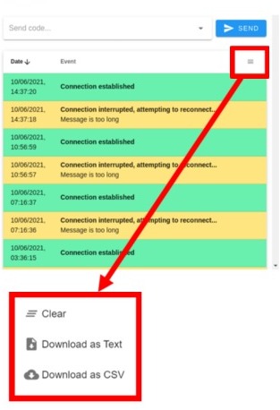
The Console provides a way of manually send G-Code commands to the printer and displays a log of responses from the system messages. Responses in the Console log are in date/time order, with the latest entry at the top.
Notifications and firmware responses are blue, warnings are orange, errors are red while some system messages are green.
The console output can be cleared, or downloaded as a plain text or CSV file, from the drop-down menu on the right.
You can connect a keyboard to the Macro Unit in one of the two USB ports located on the right side of the Printer for entering command codes.
Height Map

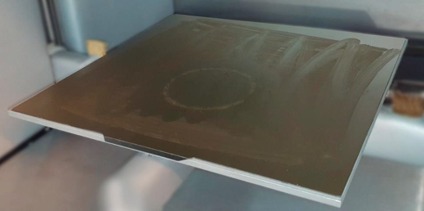
The Height Map screen displays the bed mesh compensation results. The view shows the statistics of the bed mesh and some control over the display.
The image shown is an exaggeration of the build plate calibration, it has a mean error of 0,174mm (negligible error), pretty well-calibrated.
Holding the mouse over a particular point on the mesh will show its X, Y, and Z coordinates (this feature is only available in the computer interface).
Jobs
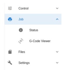 Status - Screen for monitoring the progress of the current job. The status page does not display any useful information until a print has started. Once a print has started it shows information about the file being printed, layer times, and estimates for the print time remaining. It also allows for fan, extrusion ratio, and print speeds to be adjusted in real-time.
G-Code Viewer- it shows the G-Code file

Status
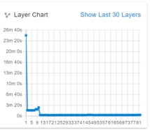
- Layer Chart
Indicates the statistical time that a layer takes to print.
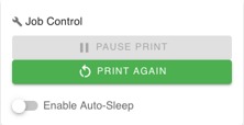
- Job Control
The Job Control palette allows the print to be paused:
Once the print is paused it can be resumed, or canceled.

Once the print has finished, you can Print again to repeat the print.
Z-Babystepping
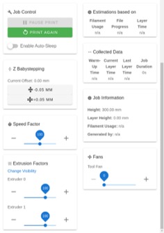
- This allows for the Z-axis to be lowered or raised by small steps - sometimes known as "Baby Stepping". This allows for small corrections to be made, usually to get the first layer perfect. Normally this is not needed if correct build plate calibration has been made, perhaps some materials will need an adjustment if the user prefers. This value will remain until the printer has been power-cycled. The user does not need to reboot the printer to reset the Z babystepping settings.
Estimations
It relies on the selected file to provide estimated data.
Collected data
Shows statistics for the current print. Warm-up time is the amount of time before the print starts.
Job information
- The data gets pulled from the file being printed and filament usage estimates are generated. It’s useful for statistical data recollection and statistics. Inaccurate data on the file (given when the model was sliced) will lead to misleading information.
Speed Factor
Allows the user to modify the print speed using a speed multiplier.
Fan Control
Allows the user to modify the hotend cooling fans using a speed multiplier. Click Change Visibility to show other fans configured in config related to the currently active tool’s print cooling fan (as different tools may use different print cooling fans etc). Thermostatic fans are not displayed.
Note: This new feature will be available soon
Files
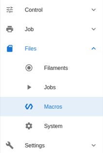
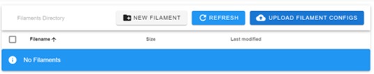
Filaments - The filament control screen. Filament profiles can be created, uploaded, downloaded, edited, renamed, and deleted.
Jobs - List of G-code files on the SD card, with details. More information later.
Macros - List of macros. These files should not be modified, edited, or deleted unless a Smart3D representative technician suggests so.
System - List of system configuration files. These files should not be modified, edited, or deleted unless a Smart3D representative technician suggests so.
- Filament:
The filaments page allows for the configuration of filament types and their associated load and unload macros.

Use the buttons to create a new filament, refresh the list or upload a filament configuration (feature only available in computer interface).
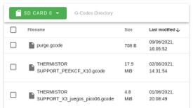
- Jobs:
The Jobs page will show the available files on the SD card to print.
Settings
This section shows 2 main features:
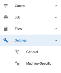
- General
- Machine-Specific
General: This screen shows appearance and interface settings such as:
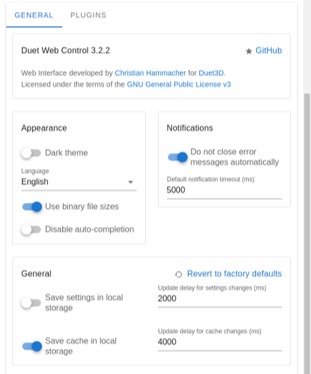
- Appearance - Switches dark theme on/off
- Language - If English is not the preferred language, it can be changed here.
- Use binary File sizes - This should not be modified.
- Disable auto-completion - It allows or disables the auto-completion of command lines when using the console.
- Notifications - It controls the display of pop-up notifications
- Default notification timeout - Controls how long a pop-up will be kept up. After this time, the pop-up will close automatically.
- General Should not be modified unless asked by a Smart3D Technician or certified representative.
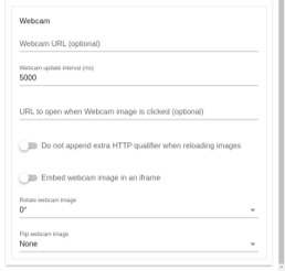
The webcam will be available in future firmware releases.
Machine-Specific - This screen shows settings for the machine, and how the Mainboard Web Control interacts with it. It includes baby-stepping, increment/decrement in mm, and feed rate in mm/min for all axes. These section features should not be modified, edited, or deleted unless a Smart3D representative technician suggests so.
How to access the Help Center
- Go to support.smart3d.tech using your preferred web browser.

- Click on 3D PRINTERS & DRYERS.


Now you have access to all public material on our 3D Printers and Dryers.
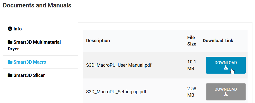
User manual
Provide the end-user with the User Manual which can be downloaded from here.
Also, provide the end-user with your customer support contact information.
Macro PU Maintenance
Maintenance Guide
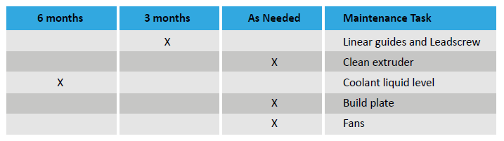
Maintenance tasks must be performed on a regular basis in order to maintain optimal system operation.
General Maintenance
The complete maintenance guide can be downloaded from here:
Extruders
Check both extruders periodically as filament debris can accumulate around them. Perform a quick inspection of the hotends every two (2) weeks and a thorough inspection every two (2) months. During the thorough inspection, be sure to check for dust or debris in the extruder gear. If dust or debris is present, use the provided brush.
1. First, be sure to check the surroundings of the extruders. If there is much debris accumulated, it will be easily spotted below them.
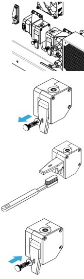
2. There is no need to remove the extruder to carry out the cleaning procedure. Remove the thumbscrew tensioner to access the internal gears.
Note: It is recommended to count how many revolutions the screw had.
3. Using a brush, gently clean the inside of the Bowden and the gears. Removing any residue will improve the grip of the extruder and will minimize the risk of cross-material contamination when printing.
4. Insert back the thumbscrew tensioner and be sure to screw in the same amount of revolutions it had.
Note: if you don’t know how many it had, apply three (3) full screw revolutions clockwise.
Linear guides and leadscrew
IMPORTANT: Make sure the Macro 3D Printer is turned off and unplugged from any and all power sources to avoid any accidents.
To access the leadscrew of the Macro unit, please follow these instructions.
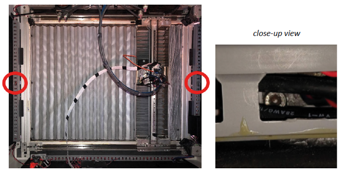
- Open the top door.
- Located and remove the screw inside the rail on the left side of the unit (see images) using a 3mm Allen wrench. Be careful not to damage the surrounding cables.
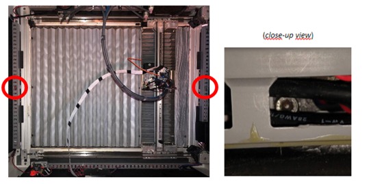
- 3. Remove the 3 bottom screws that secure the side panels using a 2.5mm hex key.
WARNING! Be careful not to damage dangerous electrical parts with higher voltages (220V/230V).
You will need to perform maintenance on both linear guides and leadscrews every three (3) months (or more frequently during heavy use).
- Apply bearing grease on the linear guides with a brush
- Apply high-temperature grease onto the leadscrew nut and raise the leadscrew to distribute the grease correctly
Leadscrews
- Apply a small amount of high-temperature grease on each leadscrew nut and raise the leadscrew.

- Once you have applied the grease to both leadscrews, turn on the printer and move the build plate up and down all along the printing area.
To do this, press HOME ALL, send the command G1 Z400 on the upper command bar and press HOME ALL again.
- Turn off the printer.
Guidelines
- Apply a small amount of bearing grease along the side of each rail.
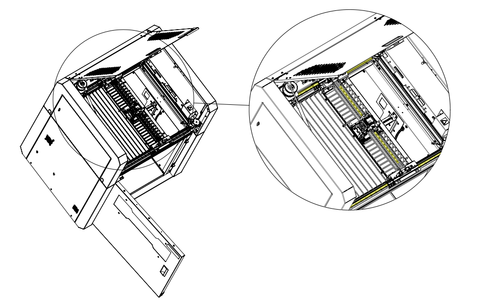
- Move the printhead all over to lubricate the guidelines properly.
To do this, Turn ON the printer and press the buttons HOME X and HOME Y
On the upper command, bar send the following command G1 X345 Y345
Coolant liquid level
- Make sure your unit is powered off and open the top door.
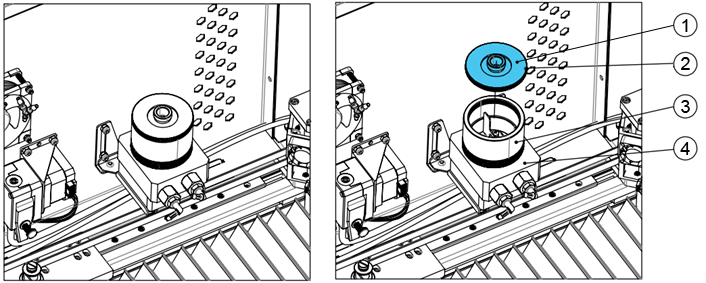
- Inside the top compartment, remove the reservoir top and be careful not to lose its O-Ring.
Picture reference:- Reservoir top
- O-Ring
- Reservoir
- Water Pump
- Fill the cooling reservoir only using Smart3D-approved coolants.

CAUTION: Wash your hands if you come into contact with the coolant and avoid touching your eyes, nose, or mouth. Note: Liquid coolant from Smart3D contains chemicals that inhibit microbiological growth (and subsequently corrosion). Tap/Bottled/Purified water is an ideal environment for microorganisms to grow which will reduce cooling, be difficult to clean up, and could lead to hardware damage.
4. Open the cooling system stopcock.
5. Turn on your unit and let the coolant flow through the tubes.
Keep filling the reservoir to the specified max level (see image) until the coolant in the reservoir no longer drains when the unit is on.
Then put on the reservoir top and open the fill port.
After filling up your cooling system, we recommend letting your unit run for at least 30 minutes without printing with the fill port open to vent as many air bubbles as possible. This will help improve the longevity of your cooling system.
When completed, close the fill port.
Note: Check on your coolant level once or twice a year and refill if necessary.
PEI Print Bed
After every print, you must clean the print bed properly. It is important to keep the bed clean and without any irregularities to prevent issues with the next print and to make sure it is aligned relative to the platform.
During the use of the printer, the print bed may get scratched. You can prolong its serviceability by cleaning it with Isopropyl alcohol using a clean cloth.
How to clean the PEI Print bed
Note: If the printer has recently finished printing, use the corresponding protective gear to avoid possible burns.
- Remove the PEI sheet from the bed.
- If a print was recently made, please remove it by flexing the PEI sheet.
- Moisturize a microfiber cloth with clean water and use it to clean the PEI sheet. Use abundant water if necessary. Then, use Isopropyl alcohol to do a final clean on the PEI sheet. Acetone can be used to remove leftovers or grease that cannot be cleaned with alcohol.
- If a print job is about to be sent, you can apply the corresponding adhesive at this stage before putting the PEI sheet back into the print bed.